The NOVA DVR XP CONTROL PANEL UPGRADE (SKU: 55523) is a very easy upgrade to undertake and a worthwhile option.
- First, check that your present system software level is Version 6.06 or a higher level. The version number is shown briefly, on the display, at time of applying power to the lathe.
- THEN DISCONNECT THE POWER CORD before starting any work on your machine and wait 2 minutes for the electronic circuits within lathe to discharge.
- Now, all you require is the correct screwdriver, a Philips Head #2 or a Pozidrive #2 will also suffice.
Stage 1.
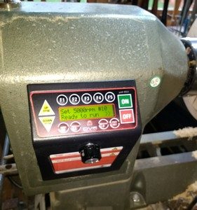
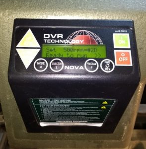 This is a picture of the ORIGINAL PANEL on your DVR-XP which is to be upgraded. This assembly has to be removed, see Stage 2.
Stage 2.
- First, locate the 2 screws on each side of your current control panel and loosen all of them, the screws do not need to be removed completely.
- The panel can be removed with a gentle forward pulling motion.
- If you pull the old Control Panel completely away from the lathe body you will find it connected via a grey ribbon cable with a RED Edge.
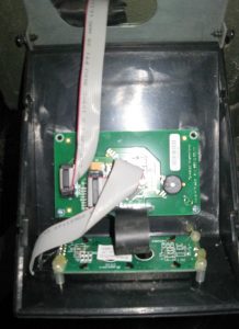
- This picture shows the interior of the display/control panel that you are about to replace.
- The cable that is to be disconnected is the one shown from the Lathe, Headstock end, with a RED Edge on one side.
- Unplug the cable without removing the Board Header Shroud.
- Put old assembly to one side or store it away.
Stage 3.
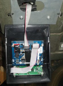
- Now connect the new assembly to the Red Edged cable discussed in Stage 2, it comes from your Lathe Headstock.
- Now go to Stage 4 unless you have the same problem that I encountered, see below.
- WARNING my new assembly came with a ribbon cable already mounted on the display/control board. That “ribbon cable has been HOT GLUED to the Board Header.” Now, this can be a problem for those who are not electronic technicians. It is however simple to fix, see Stage 4.
Stage 4.
- The problem of “the ribbon cable being HOT GLUED to the Board Header.”
- The solution is to gently pull the NEW Cable & Boarder Header away from the blue printed circuit board of your new assembly. BUT MAKE SURE YOU REMEMBER WHERE Pin 1 on the Ribbon Cable is located. The Red Edge of Cable is Pin 1 from your lathe.
- The Board Header has a NOTCH or KEYWAY in the centre of the body on one of the long sides. This NOTCH defines where Pin 1 will be located as there is a matching KEY on the plug body.
- Then remove the Hot Melt Glue by peeling it off with a knife from around the Ribbon Cable Header and the Boarder Header. Separate them, putting that cable aside as you do not need it.
- Now place JUST the Board Header back on the blue printed circuit board ensuring it is correctly shrouding all the pins and that Pin 1 is aligned per the photograph in Stage 3.
- Now connect the new assembly to the Red Edged cable discussed in Stage 2 that comes from the lathe Headstock.
Stage 4.
- Check your cable is correctly seated on the blue printed circuit board.
- Place the complete new assembly on to the side of your lathe and secure the 4 screws that were undone in Stage 1.
- Apply the electric supply and switch on. The screen will scroll through its various messages and then show your startup speed, normally 500 RPM, not 5,000 RPM as in the photograph.
- I discovered my lathe would now do 5,000 RPM whereas before the upgrade the top speed 3,500 RPM.
- Now enjoy the benefits of being able to adjust your speeds by twiddling a knob.
- You can now also add a Remote Control, this will be covered in a future post.
If you want to know where to buy the upgrade contact Teknatool website
thttps://www.teknatool.com/product/nova-dvr-xp-control-panel-upgrade/